Vertical Axis, Dual
Blade Mag Lev Wind Turbine (con't)
Power Distribution:
The power will be distributed to the BCM, SCM and SIOC units
via a power distribution network which will run alongside
the data communications cable. For the final, field deployed
system, an integrated cable combining power wires and the
data network wires will be used.
Power Consumption: The decision
to use a single power source for entire system was based
on ease of maintenance. One chargeable battery should be
capable of powering a system for over 5 years without maintenance.
Power consumption by the SIOC, SCM and BCM units is a function
of the frequency of usage (traffic on the bridge). The system
will be designed to go into sleep mode when there are no
tasks to be performed. Whenever traffic is on the bridge,
the system will wake up to start monitoring and sampling
the sensor data. Power consumption will reach peak only
when the system is in use. At this stage, estimations are
made on assumptions of usage by the SCM and BCM. In Phase
II, a re-chargeable 12 volt battery will be used. When the
system is tested on a bridge in the CFC-WVU lab, the constants
will be determined for the power consumption model. The
following formula will be used to calculate the power consumption
(Pt):
where
Pt = Pi * Zi + ( 1 –
Pi)*Za
PT = total power consumed
Pi = power consumption in idle state
Zi = probability of node in sleep mode.
Za = Probability of node active
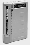
For Phase II, a 6-12TLA stationary modular
battery (Fig 5.x) from AGM Technology will be used and integrated
with a 12V, 700mA, portable briefcase solar generator To
trickle charge the battery(Fig 5.x). The battery will be
installed in the BCM’s enclosure. Along with the battery,
the enclosure will include electronic interface between
the solar panels and the battery, to ensure the battery
is not damaged by over-charging.
Designing a power supply system for a
bridge monitoring application requires knowing the power
consumption, current draw rate, and the anticipated maintenance
cycle duration and deployment environment (such as the safety
of solar panel against theft), and the anticipated battery
life (such as 5 to 10 years without maintenance).
Each hardware component will consume
2 to 5 watts of power and will require 2 amps (peak) of
current. The goal will be to provide a minimum of 5 years
of uninterrupted, regenerative power to the system. This
will be achieved using two options (both options would provide
the same amount of power):
Solar panels: In safe and stable
areas, solar power panels will be implemented. These panels
are inexpensive; however, they can be easily stolen or
targeted.
Fuel cell batteries: In where
environments where tampering and targeting are issues,
low cost fuel cell batteries could be deployed. Their
advantage is that they can be hidden in the bridge structure
itself. They are already in limited use by the DOD. The
disadvantage is that they are more expensive than solar
panels.
A wide variety of options for solar and
fuel cells will be reviewed in Phase II: from simple sealed
lead acid battery packs to complex Lithium-ion packs that
include electronic safety, monitoring, and charge-control
circuitry. Critical issues, such as cost, packaging, eco-environmental
factors, and regulations affecting battery-pack design and
construction will be considered, as well as bridge parameters,
like bridge length, number of bridge sections, number of
sensors, and anticipated traffic volume.
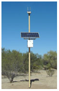
Solar Power: Solar panels
are one option for recharging the batteries. The solar charging
system will be rated for 12 volts and a minimum of 20 watts
of power, which is sufficient for
recharging any battery. In Phase I detailed analysis of
the availability of solar chargers was conducted. The conclusion
reached was that solar is the most economical and practical
option for this application; however, its disadvantage is
that solar panels can be easily stolen or used as a target,
which would render the system useless without power. The
solar configurations would include a solar panel installed
on a pole, which could also serve as an antenna. (Figure
1) is a diagram of solar backup system includes a solar
panel that charges a battery. The solar panel is connected
to a regulator to protect against overcharging and damaging
the battery.
Battery Chemistry: Today, the choice
is typically one of three rechargeable cell types: Nickel-metal
hydride (NiMH), Lithium-ion (Li ion), and Lithium-polymer
(Li-polymer). Li-polymer’s advantages are higher energy
density by weight than Li ion and higher volumetric energy
density in thin formats using less than 5mm cell thickness.
Unlike other chemistries that are typically available in
limited standard sizes, Li-polymer is available in any footprint,
which will provide greater flexibility during design. Li-polymer’s
stability in over-voltage and high temperature conditions
provides a wider margin of safety than with Li-ion. Li-They
are also weatherproof.
Fuel Cell Battery: An electrochemical
cell in which the energy of a reaction between a fuel, such
as liquid hydrogen, and an oxidant, such as liquid oxygen,
is converted directly and continuously into electrical energy.
In addition to this pure hydrogen type, there are hydrocarbon
fuels for fuel cells, including diesel, methanol and chemical
hydrides. The waste products with these types of fuel are
carbon dioxide and water. The materials used in fuel cells
differ by type. In a typical membrane electrode assembly
(MEA), the electrode–bipolar plates are made of metal,
nickel or carbon nanotubes, and are coated with a catalyst
(like platinum, nano iron powders or palladium) for higher
efficiency. Carbon paper separates them from the electrolyte,
which could be ceramic or a membrane. UltraCell Corporation
of Livermore, CA offers a 12 volt fuel cell (Figure 2)
that provides 12 volts power with total energy capacity
(per charge) of 180W.
The sensor networks will be designed for
deployment in adverse and remote/non-accessible areas that
may not have fixed infrastructures. Power harvesting technology
extracts energy from relatively inexhaustible ambient sources,
such as wind, temperature, vibration and other natural phenomena,
to provide power to the sensor nodes. Additionally, energy
usage optimization will be employed, based on previous work
developed by Erallo for a MEMS-based sensor application.
A number of power harnessing technologies will be reviewed
and considered for this application; including solar and
vibration energy. Harnessing an ambient energy sources like
vibration may even eliminate the need for batteries in many
monitoring applications. This would extend the useful life
of the sensor system and significantly reduce the lifetime
cost of the sensors.
Vibration Energy Harvesters (VEH):
The two most widely studied classes of vibration energy
harvesters (VEH) are inductive and piezoelectric. Inductive
VEHs work on the principle of the magnetic generator of
Faraday’s law, with the external input energy coming
from the ambient vibrations. The vibrations generate a displacement
between a permanent magnet and a pickup coil, generating
voltage in the coil. The voltage is rectified and delivered
either to a storage device or directly to a load.
Inductive VEHs are well suited for use
with lower frequency vibrations (below a few hundred Hz).
Inductive VEHs are robust and can survive significant temperature
and shock extremes and are ideal for battlefield environment.
Inductive devices can last for decades with little or no
degradation in performance.
Vibration based power harnessing:
Our adviser for this technology will be Dr. Robert O'Handley,
Chief Scientist and Co-Founder of Ferro solutions. Ferro has
developed a suitable vibration generator (Figure 3),
called VEH-3. These units will be used in experiments to analyze
their suitability for BMS applications. These units are currently
being used by the Navy to power sensor networks in ships and
submarines. Ferro Solutions has a plans to modify and fine
tune the generator in Phase II, if required.
Solar power: Self-contained, portable
solar power generation systems will be considered as an
alternative to vibration power generation. These devices
are built like a generator, with everything except the 50-watt
solar panel contained in one attractive enclosure. These
solar devices can power a 12 volt battery charger and can
provide 50 Watts of power. This would be sufficient for
powering sensors as well as the BCM. A detailed analysis
of the daily power draw from the sensor module and BCM module
will be conducted so that an appropriate solar power unit
can be identified and analyzed.
Power storage: Energy storage is
comprised of a group of elements used to buffer the energy
coming from the power generator (Figure
4) and deliver them to the mote in a predictable
fashion. Designing the energy storage involves choosing
the storage elements and charging mechanism for correct
operation and efficient energy transfer while satisfying
a set of system requirements such as lifetime, capacity,
current draw, size and weight. For the energy storage element,
NiMH (Nickel Metal Hydride) or Li+/Li-polymer (Lithium-ion
/ Lithium polymer) batteries are desirable due to their
high energy density while super capacitors are desirable
for their high charge cycles.
Figure 1 Photo of a solar panel recharger
and diagram illustrating a solar backup battery system
Figure 2 UltraCell Fuel Cell Cartridge
Figure 3 Ferro Solutions’ Vibration
Power Generator